Description
Power Factor Correction Panel
Another type of industrial electrical panel, in terms of application, is the power factor correction panel, which is used as a بانک خازن They are also known as power factor correction panels. These panels can effectively reduce the reactive power of a system, increase its efficiency, and ultimately lower electricity bills for industrial units while reducing system losses.
Power factor correction bank (capacitor bank)
In industrial units, because most of their consumption is inductive, they use not only active power but also reactive power. For example, the windings of electric motors consume both active (useful) power and reactive (non-useful) power to perform work and rotate the motor. As a result, this increases the line current, raises power losses, and lowers the power factor. This phenomenon causes the power that the source must generate to be higher than the actual demand of the consumer. Consequently, the electricity provider may impose a penalty for the losses caused to the network, which can lead to significant additional costs.
Capacitor banks are widely used as an electrical equipment in industrial power systems because most of the energy consumed in industry comes from motors, which causes issues such as increased current and the need for larger cable and wire sizes. Therefore, the best solution to mitigate these problems is to add a capacitor bank panel to the circuit. In some cases, capacitor banks are also used to assist motor startup and to balance loads in three-phase networks.
Improving the power factor is another reason capacitor bank panels are used in industry. These panels, thanks to their ability to regulate and stabilize voltage, help prevent damage to industrial machines and equipment. To control the power factor, regulators are used in the panels to measure the waveform and the phase difference between voltage and current. Based on these measurements, the required capacitor capacity is determined, and when connected to the network, the panel corrects the power factor.
In industrial units, since most of their consumption is inductive, they use reactive power in addition to active power. For example, the windings of electric motors consume both active (useful) power and reactive (non-useful) power to perform work and rotate the motor. This leads to an increase in line current, higher power losses, and a reduction in power factor. As a result, the amount of power that the source must generate becomes higher than the actual consumption requirement. Consequently, the electricity authority may impose penalties for the damage caused to the network, which results in significant additional costs.
Therefore, to reduce line current and voltage drop, increase the power factor, and consequently compensate for reactive power, capacitors are used. This process is called power factor correction.
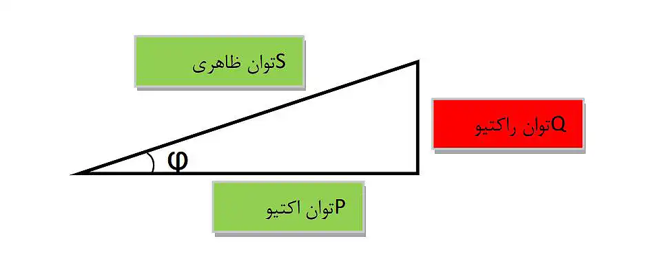
The power factor is obtained by dividing the active power by the apparent power:
COSφ= P/S
In the power triangle, it can be seen that the closer the angle φ is to zero, the closer cos φ gets to one, which results in a reduction of reactive power.
Ultimately, if cos 0° equals one:
COSφ= P/S => COSφ= 1
This means that the active power equals the apparent power, i.e., the two sides of this triangle overlap, which results in the reactive power becoming zero.
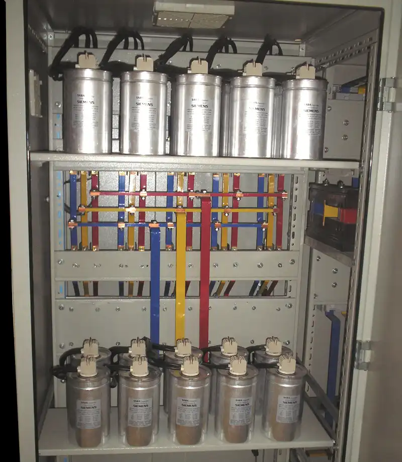
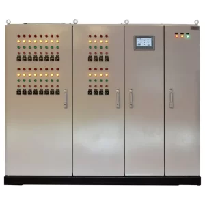
Main Equipment of a Capacitor Bank
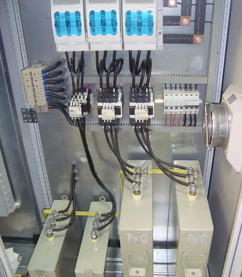
- Main switch: A capacitor panel, like other electrical panels, has a main switch to protect the current and prevent short circuits for all the equipment inside the capacitor panel. Usually, automatic compact switches or cartridge fuse switches are used as the main switch.
- Busbar The busbar is made of copper and is used for branching and supplying power, allowing a single power source to feed multiple loads and consumers.
- Fuse: To protect each capacitor step, a properly rated fuse must be installed at the beginning of each capacitor line. Protective devices used in this section can include cartridge fuses, compact switches, or, for lower ratings, miniature circuit breakers.
- Capacitor Contactor: These are contactors specifically designed for capacitors, equipped with resistors or inductors to reduce and limit the inrush current of the capacitor. The type of these contactors is ACB6, and their typical ratings range from 7.5, 12.5, 15, 20, 25, 50, to 60 kVAR.
- Capacitor: They are used to correct the power factor of electricity consumption in an industrial or residential facility.
Operation of a Capacitor Bank
Each capacitor step consists of a fuse or three-phase switch, a capacitor contactor, and a capacitor. All capacitors are controlled by their contactors via an intelligent device called a capacitor regulator. This device measures the total current passing through the unit using a current transformer, processes the information, and based on the load or current consumption at any given moment, it connects the required number of capacitor steps to the circuit and disconnects the unnecessary ones.
Therefore, the capacitor regulator plays a very important role in power factor correction systems or capacitor banks.
Guidelines and Recommended Schedule for Service and Maintenance of Capacitor Banks
- Tightening and ensuring that all connections and screws are secure (every six months): Loose connections, screws, busbars, and wires can cause sparks and intense heat at those points. As a result, the current does not pass efficiently, which can lead to damage or even explosion of the capacitor. Over time, the heating and cooling of screws can cause them to loosen.
- Inspection and verification of the proper condition of all fuses (weekly): One of the common issues in capacitor banks is fuse burnout, which often occurs due to the inrush current of the capacitor and the momentary surge when connecting to the network. It is recommended that capacitor banks use automatic switches with high breaking capacity or premium cartridge fuses with high breaking capacity.
- Proper ventilation and inspection of the fan and thermostat (monthly): The likelihood of fan failure due to dust penetration is quite high, and if the fan stops working, the panel temperature will rise. This increase in temperature can have adverse effects on the capacitors, fuses, and the regulator.
- Cleaning the air vent filter (monthly): The filters installed in the ventilators to prevent dust penetration will quickly become clogged with dust, blocking the pores and preventing proper air exchange.
- Sealing the cabinet vents to prevent dust ingress: The cabinet vents and doors must be completely sealed to minimize the ingress of dust. Dust accumulation over time can lead to the malfunction of the regulator and especially the contactors.
- Blowing off and cleaning dust from panel components (monthly):
- Measuring capacitor capacity (annually):
- Ensuring the proper operation of the control circuit of the panel: For this purpose, each capacitor step can be manually switched into the circuit one by one using rotary switches and the regulator. However, if the main line does not require capacitors, it is better to disconnect the capacitor protection fuses during testing of the control circuit.
- Ensuring the integrity of the contactor’s power contacts: The output power of the contactor can be easily measured using a voltmeter to ensure its proper functioning, as there is a possibility of contact welding or even burning of one of the contactor’s contacts.
- Blowing out the contactor coils: Usually, over time, dust enters the contactor coil housing and accumulates between the fixed and movable iron cores. The simplest way to detect this is by hearing a vibration or buzzing sound in the contactor. Additionally, after blowing out the dust, it is recommended to clean the space between the two cores with a thinner-soaked cloth to remove any grease.
- Measuring the total current of the panel (every month): To ensure the health and proper functioning of the capacitor bank, it is recommended to measure the instantaneous current of the capacitors under load using a clamp ammeter and compare it with the nominal current.
- Ensuring the correct connection of the cable from the current transformer to the regulator: For this, you can use the current parameter available on the regulator to monitor the power circuit current. If the current transformer connection to the regulator is incorrect, the current will read zero and the regulator will display an error.
Reviews
There are no reviews yet.