Description
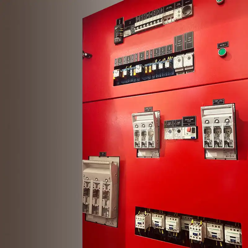
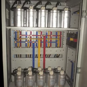
The fire-fighting booster pump control panel is the heart of the fire water supply system. This panel is responsible for controlling and directing the pumps to provide water at the proper pressure and flow rate for extinguishing fires. The fire booster pump panel consists of various components, some of which are highlighted below:
- Controller: The controller is the brain of the control panel and is responsible for managing and directing the pumps. It can operate either manually or automatically.
- Contactor: A contactor is a key device that connects and disconnects the electrical current to the pumps.
- Fuse: Protects the pumps against overload and short circuits.
- Relay: Transfers control signals from the controller to the contactors.
- Pressure valve: Used to regulate the water pressure output from the pumps.
- Pressure gauge: Used to display the water pressure output from the pumps.
- Siren: Used to provide an alert in case of a fault in the fire-fighting water supply system.
The fire-fighting booster pump control panel should be installed in a location that is easily accessible and protected from weather conditions such as rain, snow, and dust. It should also be regularly serviced and maintained to ensure proper operation.
Types of Fire-Fighting Booster Pump Control Panels:
Fire-fighting booster pump control panels are available in various types, each designed for a specific application. Some of the most common types of fire-fighting booster pump panels include:
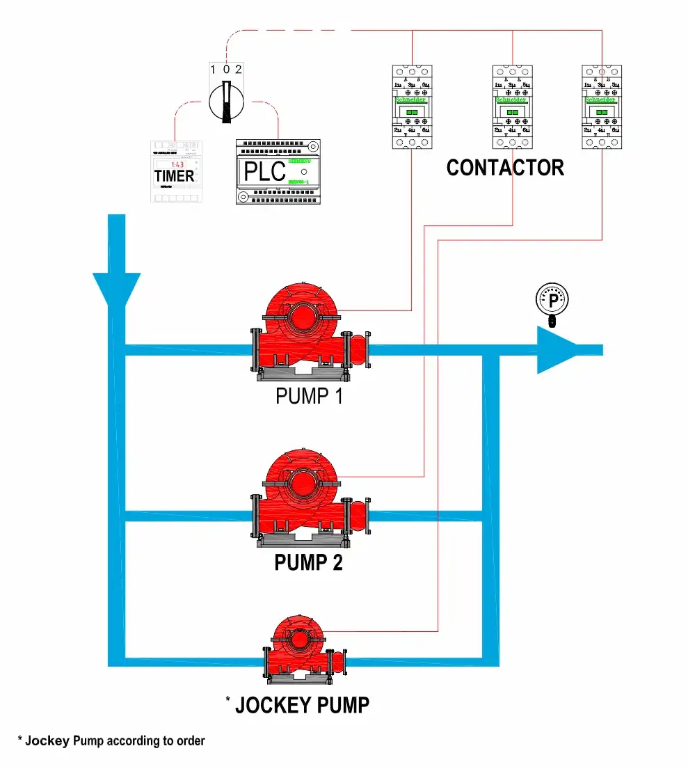
Single-Pump Booster Pump Control Panel
Two-Pump Booster Pump Control Panel
Jockey Pump Booster Pump Control Panel
Diesel Booster Pump Control Panel
Choosing the Right Firefighting Booster Pump Control Panel:
Selecting the appropriate firefighting booster pump control panel depends on various factors, including:
Firefighting water supply system capacity: The capacity of the firefighting water supply system is determined based on the number of fire hydrants, the required flow rate for each hydrant, and the maximum height of the building.
Pump type: The type of pump used in the firefighting water supply system (single pump, two pumps, jockey, diesel).
Environmental conditions: Environmental factors such as ambient temperature, humidity, and dust levels must be considered when selecting a firefighting booster pump control panel.
Advantages of using a firefighting booster pump control panel:
Using a firefighting booster pump control panel offers several advantages, including:
Increase in water pressure: A firefighting booster pump control panel can significantly increase water pressure, which is essential for effectively extinguishing fires.
Increase in water flow rate: The fire pump booster panel can significantly increase the water flow, which is essential to ensure sufficient water supply for extinguishing fires.
Water consumption reduction: The fire pump booster panel can significantly reduce water consumption by regulating both water pressure and flow rate.
Safety Improvement: The fire pump booster panel, by ensuring water is delivered at the proper pressure and flow rate for firefighting, helps enhance the safety of the building and its occupants.
Equipment Protection: The fire-fighting booster pump panel, by regulating water pressure and flow, prevents damage to the pumps and other components of the fire water supply system.
Ease of Use: The fire-fighting booster pump panel is designed for easy operation and straightforward maintenance.
Important Points Regarding Firefighting Booster Pump Panels:
Selecting the appropriate electrical panel: Choosing the right fire booster pump panel is extremely important. It is recommended to consult an experienced specialist to select the appropriate panel for your firefighting water supply system.
Proper installation: The fire pump booster control panel must be installed by an experienced electrician.
Service and Maintenance: The fire pump booster control panel must be regularly serviced and maintained to ensure its proper operation.
Periodic Testing: The fire pump booster panel must be tested periodically to ensure its proper operation in case of fire.
Features of fire department–approved electrical panels
- The dimensions of the electrical panel must be such that sufficient space is available for installing panel equipment with appropriate clearances to allow for future repair, servicing, and maintenance. In addition, 15% of free space should be considered to allow for future expansion of the panel.
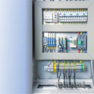
- For routing communication wires between panel equipment, plastic electrical ducts of appropriate dimensions must be used in such a way that sufficient space, along with 15% free space, is available for wire passage or replacement. In addition, all electrical connections must be made using wire ferrules and cable lugs.
- The conductor used in the cables must be made of copper, and the cables must be installed continuously without splices, in a single piece.
- At the cable entry and exit points, cable glands should be used, and for steel conduits, brass bushings should be installed.
- The pumps must be equipped with a self-service system in accordance with fire safety regulations and should be activated at adjustable time intervals.
- The panel equipment used in the construction of fire-fighting booster pump control panels must comply with recognized international standards.
- The miniature circuit breakers (MCBs) are of Type C, suitable for motor loads.
- Pump startup up to 7.5 kW is done using direct-on-line (DOL) method, while for powers of 11 kW and above, a star-delta (Y-Δ) startup method is used.
- The use of soft starters and inverters for pump startup is not permitted; pumps must be started using contactors for continuous operation.
- The use of automatic circuit breakers in the electrical panel is not allowed, and non-switchable fuse-type breakers must be used at the power circuit input.
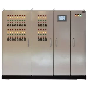
- The panel enclosure must have an electrostatic powder-coated finish in RAL 3020 and include a rubber gasket. The sheet metal thickness should be 1.5 mm, with a minimum paint thickness of 90 microns. The paint is tested before the panel is delivered to the customer.
- The panel must have a minimum protection rating of IP54 and be equipped with a hinged cover.
- The panel body is connected to the grounding system and earth, but this does not affect the operation of the pumps.
- The panel is equipped with an automatic lighting system that activates when the panel door is opened.
- Firefighting electrical panels must be installed in a suitable location. The appropriate location for installing a fire alarm electrical panel is one that offers high safety and minimizes the risk of accidents and fire.
- The main intelligent control and command system of the panel, in accordance with the unique scenarios and operating requirements of the Fire Department, is designed to control the pumps and self-service functions using a Siemens original PLC and EXP (for input/output), along with a 7-inch display featuring an Ethernet output. Additionally, event logs and reports related to pump performance, tank level, and self-service operations can be extracted directly from the PLC.
- The fire-fighting control panel is equipped with a pneumatic siren to announce all alarms and faults.
- The use of any protective devices, including thermal overload relays (bimetal) and phase control relays, in the main pump power circuit is not permitted. Such conditions are only transmitted to the PLC as a fault signal, which in turn activates the pneumatic siren to alert the operator.
- The panels receive an input from the fire water tank level monitor. If the water level drops below the permissible limit, a fault signal is sent to the fire alarm control center, and the pneumatic siren is activated to notify the operator of the situation.
- The wire color coding in panels approved by the fire department is as follows:
| Wire | Color |
|---|---|
| Phase 1 | Red |
| Phase 2 | Yellow |
| Phase 3 | Black |
| Neutral Conductor | Light Blue |
| Protective Conductor (PE) | Green / Yellow |
- The panel is equipped with a document pocket for storing related manuals and wiring diagrams.
- The panel is equipped with power and control circuit diagrams along with the layout of electrical components.
- For the S1 group, all electrical equipment is assembled within a single panel, whereas for the S2 and S3 groups, a separate frame is allocated for each main pump according to fire department regulations (a total of two separate frames). Each panel must have its own dedicated circuits.
- S2-S3 group panels are equipped with an HMI display to view event logs, pump performance, and any potential faults in the self-service system.
- To prevent the jockey pump from operating repeatedly to compensate for minor pressure drops in the system, a suitably sized pressurized tank is used.
- The pressure switch is selected according to the water medium and is installed on the discharge line, between the check valve and the shut-off valve. No shut-off valve should be placed in the pressure switch line. Additionally, the pressure switch is mounted on a loop pipe with appropriate pressure.
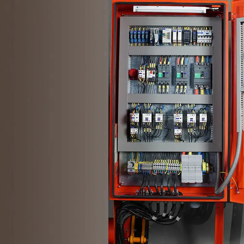
The fire pump control panel is the motor control panel in a fire pump booster system. The main components of the control panel include: Contactor، Bimetallic relay، Thermal switch، Miniature circuit breaker،Automatic main switch With brand SchneiderFan: bearing typeTerminal and rail ها Raad And the enclosure has an IP54 protection rating, made of 1.5mm thick sheet metal with electrostatic paint, and includes:
- Intelligent control system
- Main rotary switch beside the panel, Schneider brand / Tavan Rah Sanat
- Key switch / vertical, MITO brand; phase control, Borna / Shiva brand; fan vent, MITO / OSKAR brand.
- Cable brands: Zarsim / Khorasan / Hamedan / Ri Afshan.
- Speed control using Danfoss inverter (in variable-speed models)
- The panel is equipped with a Delta PLC with analog inputs and outputs in the variable-speed models, along with a 7-inch Delta HMI monitoring system. (Includes a 5-year warranty)
- Gradual increase and decrease of each pump's speed according to consumption, resulting in the elimination of water hammer and extended lifespan of the pump’s moving parts (in variable-speed models). Also features PID control and a unique program from Grundfos (Hydro MPCF).
- Automatic and manual selection system for testing or removing any pump from the circuit in case of a technical fault.
- Pump start slip and frequency control system to prevent pressure fluctuations.
- Self-service system in fire-fighting booster pumps.
- Auto Change Over (ACO) systems (ensuring each pump operates equally) in ON/OFF mode.
- Time Changing
- Signals the system and shuts it down when there is a water shortage in the circuit, and automatically restarts once the water shortage is resolved.
- Protection of the electric pumps against overload by connecting the motor PTC to the PLC, with each alarm having a separate command.
- Protection of the electric pumps for phase sequence and phase number.
- Use of a contactor and main switch rated 40% higher than the current drawn by the electric motor during direct-on-line startup.
- Control to prevent the electric pumps from turning on or off due to pressure fluctuations and to avoid simultaneous operation.
- Equal distribution of operation among all main electric pumps, so that the running time is shared evenly across all pumps.
Safety and protection systems
- Water shortage safety system in the tank, indicated via an alert on the HMI screen.
- Safety system for detecting and preventing operation of the pump without water.
- Phase control safety system to prevent phase loss and fluctuations in voltage and current.
- Ground (earthing) safety system for protection in case of phase-to-ground faults.
Reviews
There are no reviews yet.