Description
The fire-fighting booster pump, as the most critical component of a building’s fire suppression system, plays a vital role in the proper functioning of the system. Any malfunction in this unit can lead to reduced efficiency of the fire suppression system and result in irreparable loss of life and property. Therefore, using a fire pump set with valid and recognized standards is of utmost importance.
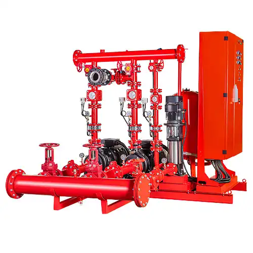
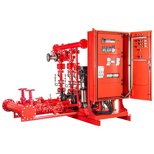
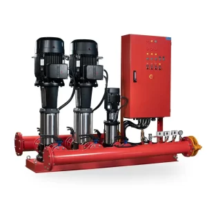
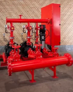
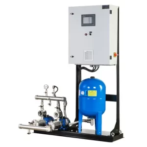
A fire-fighting booster pump is a system composed of a main electric pump, a standby pump, and a jockey electric pump, along with all necessary valves, fittings, control equipment, and an electrical control panel. It is used to provide the required capacity and pressure for fire protection systems.
Proper operation and high performance of the fire protection system require full compliance with all fire safety rules and regulations.
Panels approved by the Fire Department are manufactured in three models:
- Model S1 – Approved by the Tehran Fire Department
- Model S2 – Approved by the Tehran Fire Department
- Model S3 has UL/FM certification based on the NFPA-20 standard.
Price of Fire-Fighting Booster Pumps and Influencing Factors
Fire-Fighting Booster Pump Selection Guide
Pump Sizing
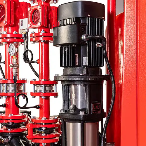
The fire-fighting booster pump must be equipped with horizontal centrifugal pumps featuring graphite seals that allow a drip rate of one drop of water per minute from the seal. The use of any type of multistage pumps, whether horizontal or vertical, is not permitted in the construction of fire-fighting booster pumps.
A fire-fighting booster pump can be manufactured with or without a jockey pump. These pumps are used to maintain constant pressure at all times in the fire protection system, compensating for pressure drops caused by moisture and leaks from valves and fittings in the system. They also prevent water hammer when the main pump starts operating. The fire-fighting booster pump must be equipped with two main pumps, each capable of supplying the maximum required fire water flow at the desired pressure. In other words, each fire-fighting booster pump includes one main pump and one standby pump that matches the specifications of the main pump.

Booster Pump Control Point
The most important factor in selecting a fire-fighting booster pump is its characteristic curve. The most suitable pump to supply the fire system pressure is one whose characteristic curve has a relatively flat slope within the desired capacity range. The pump’s performance curve should be such that at flow rates exceeding 150% of the operating point, the pump head does not drop more than 65%. Under these conditions, changes in water consumption are accompanied by relatively small pressure changes. Although the pump efficiency in this range is relatively low, it should be noted that the fire-fighting booster pump operates under very limited usage, so the low efficiency does not significantly impact performance.
Adjustment Pressure
Since the fire-fighting booster pump is a fixed-speed pressure-boosting system, pressure regulation is very important. Pressure adjustment in the fire booster pump is done using a pressure switch. Due to the critical role of this component, it is recommended to use reputable brands. According to international standards, each of the main pumps in a fire-fighting booster pump must be independently controlled by its own pressure switch.
Each pressure switch has two settings:
- Pressure Range (Range)
- Pressure Differential (Diff)
When selecting a pressure switch, care must be taken to ensure that its pressure range (Range) and pressure differential (Diff) settings fall within the operating pressure range of the booster pump. The maximum pressure of the booster pump is set according to the pressure range (Range), and the minimum pressure is adjusted based on the pressure differential (Diff) below the set maximum pressure. These settings should be configured so that, considering the booster pump’s characteristic curve at both minimum and maximum fire water consumption: * The maximum booster pump pressure remains below the maximum pressure setting of the pressure switch. * The minimum booster pump pressure stays above the minimum pressure setting of the pressure switch. Under these conditions, the booster pump will operate as long as there is demand. Once the last fire suppression water consumer closes, the booster pump pressure reaches the maximum pressure switch setting, causing the booster pump to stop. It is important to note that for fire booster pumps equipped with a jockey pump, the jockey pump’s pressure switch must be set so that its minimum pressure is higher than the minimum pressure switches of both the main and reserve pumps. This prevents the main and reserve pumps from starting unnecessarily while the jockey pump compensates for minor leaks and losses in the fire suppression network.
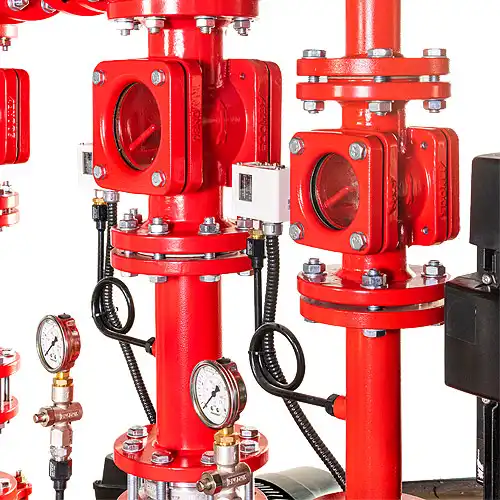
Valves
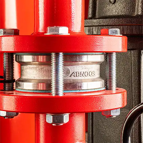
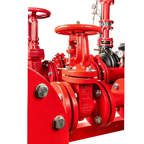
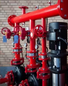
At the inlet and outlet of each booster pump, an isolation gate valve must be installed. These gate valves should be connected to the pump collectors before connecting the pump and any other attached valves. At the outlet of each booster pump, a check valve (non-return valve) must be used. The check valve prevents water from flowing back from the piping network into the water storage tank or from the outlet of any pump flowing back through the suction collector into the suction side of the pump currently running. Additionally, restrained vibration dampers (vibration isolators) must be installed at the inlet and outlet of each pump to prevent the transmission of vibrations generated by each pump to the other pumps and the piping network.
In cases where high-quality pumps, which are generally silent and vibration-free, are used in the construction of booster pumps, the use of vibration isolators is not necessary. However, to minimize the transmission of any residual vibrations, it is recommended to install vibration isolators at the connection points of the booster pump’s suction and discharge collectors to the piping network. To prevent the entry of foreign materials into the booster pump, piping network, and other water fire-fighting equipment, a shut-off gate valve should be installed at the beginning of the water supply pipe coming from the fire water storage tank, followed by a strainer with a galvanized or stainless steel mesh.
The type of shut-off valves used for the inlet and outlet of booster pump units, as well as the main shut-off valves at the booster pump’s inlet and outlet, are generally gate valves or butterfly valves. When using butterfly valves, it should be noted that since the valve opens and closes with a quarter-turn of the handle, this operation must be performed gently, especially when the pump is off or under operation. This careful handling prevents sudden pressure changes and water hammer effects in the distribution network.
The valves used in the construction of booster pumps are brass threaded valves up to 2 inches, and cast iron flanged valves for sizes 2½ inches and above. In practice, to maintain uniformity, brass valves can be used up to 4 inches as well. The class of valves and fittings used in booster pump construction must be selected based on the working pressure of the booster pump. The working pressure rating of valves and fittings should be at least 1.5 times the operating pressure of the booster pump. Considering that the factory test pressure of valves and fittings is also 1.5 times their pressure class, by following these guidelines, valves and fittings are selected with an adequate safety factor.
Collector
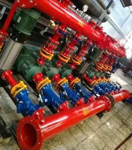
The construction of fire booster pump collectors using pipes and fittings is permissible if their pressure class is respected. However, due to the high operating pressure of fire booster pumps and to ensure greater safety margins, fire pump collectors are usually made from black seamless steel pipes. To distinguish them from other booster pumps in the engine room or pump house, after applying an anti-rust coating, they are painted with two coats of bright red finish paint.
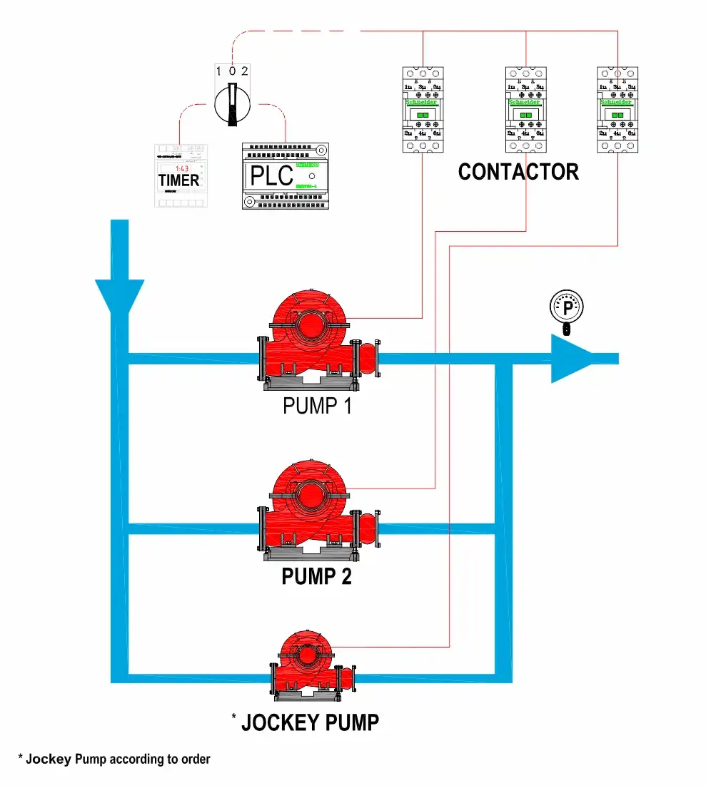
Firefighting Booster Pump Control Panel
The electrical panel of a fire booster pump is composed of various components. First and foremost, the panel enclosure must be made of black steel sheet with a suitable thickness—at least 1.5 mm—depending on the panel’s size, and should be coated with electrostatic powder paint and oven-cured. Additionally, the enclosure must have a minimum protection rating of IP-54. The dimensions of the electrical panel should be sufficient to allow for the installation of internal components with adequate spacing to facilitate future maintenance, servicing, and repairs. To route the connecting wires between the internal components, appropriately sized plastic cable ducts must be used, ensuring enough room for wire passage or replacement when needed.
The electrical panel of the fire booster pump must include signal lights or LEDs to indicate the operation of the booster system and the activity status of each individual pump. In more advanced booster pump systems, additional indicators may be present—such as lights to signal the minimum water level in the storage tank, failure alarms, or designated terminals for connecting such alarms. The electrical components used in the panel must be selected according to the power rating of the electric pumps. For electric pumps with a power rating of 15 horsepower or higher, the power circuit must use a star-delta (Y-Δ) starting method.
Installation and Start-up
The installation site for the fire booster pump must be completely level and located in an area that provides ample space for servicing and maintaining its various components, including the electrical panel and electric pumps. One important auxiliary component to consider during installation and commissioning is the diaphragm tank. This tank is primarily intended to absorb water hammer effects caused by the starting and stopping of the electric pumps. The diaphragm tank must be connected to the discharge collector of the booster pump using a pipe that matches the flange size of the diaphragm. This connecting pipe should include a gate valve (shut-off valve) at the connection point to the discharge manifold and a union fitting at the connection point to the diaphragm tank. This setup allows for easy removal of the tank from the system when the diaphragm (bladder) needs replacement. If the pressure switches of the fire booster pump are correctly selected and adjusted according to the pump’s operating point, the diaphragm tank can even be as small as 100 liters.
Servicing and Fire Booster Pump Maintenance
According to international standards, fire booster pumps must have a regular maintenance and service schedule, including daily inspections, and weekly, monthly, quarterly, semi-annual, and annual servicing. Unfortunately, despite the emphasis placed by the NFPA standard, necessary maintenance is often neglected. Therefore, it is advisable to use a self-servicing fire booster pump to ensure consistent performance and reliability.
In the self-servicing fire booster pump panel, special equipment is used to enable each of the booster pump’s pumps to automatically start for a set, adjustable duration based on the scheduled day and time assigned to each pump throughout the week. Additionally, the outlet manifold (collector) of this type of booster pump is equipped with a bypass system. This system redirects the water discharged during the self-service operation of each electric pump back to the fire water storage tank, ensuring pump activity without water being wasted or fed into the fire suppression network during routine checks.
In addition to the aforementioned equipment, a flow switch is installed at the outlet of the main fire pipeline, connected to the booster pump's discharge manifold. This flow switch is designed to detect the flow of water in the fire protection network in the event of a fire. When water begins to flow—either due to fire-related usage or electrical circuit activation—the flow switch triggers a response in the control and command system of the self-servicing fire booster pump panel. This action disables the self-service mode and switches control of the booster pump to the preconfigured pressure switches (pressure sensors), ensuring the system operates according to standard emergency protocols.
The self-servicing fire booster pump eliminates the risk of pump seizure (also known as pump jamming) by ensuring the automatic, periodic operation of the booster pumps. This keeps the fire booster system in a constant state of readiness to respond effectively in the event of a fire. For this reason, it is strongly recommended to use self-servicing fire booster pumps in building installations to ensure reliability and continuous operational preparedness.
Abnoos, Manufacturer of Fire Booster Pumps
Firefighting booster pumps are another type of booster pumps used in buildings and industries. They consist of an integrated system made up of two or more pumps connected in parallel, designed to provide the necessary pressure and flow rate for a fire protection system with minimal energy consumption and maximum efficiency.
The capacity of a fire booster pump depends on the type and number of firefighting equipment used in the building.
Abnoos is a manufacturer of fire booster pumps, complying with all firefighting regulations and standards.
Proper design according to the building, use of the best pumps, specialized design and production of control panels, and design and implementation of the booster pump body for the best and fastest performance during fire extinguishing are the results of more than 10 years of our experience at Abnoos.
The booster pump and all its components should be regularly checked by the boiler room operator. Additionally, attention to the following points is recommended:
🔹 The operating noise of the booster set should be normal and similar to the moment of startup; if any abnormal noise occurs, the cause must be investigated.
🔹 The foundation must be designed in such a way that, over the long term, the booster pump chassis does not become unlevel or lose its alignment.
🔹 Check the performance quality of the check valves, shut-off valves, and collectors.
🔹 If the water inside the tank is drained and then refilled, the pumps must definitely be vented (air must be purged from the pumps).
🔹 The air pressure inside the diaphragm tank should be monitored by the operator, and the diaphragm's integrity must be ensured.
🔹 Due to the sedimentation of minerals inside the water pipes, after some time, the settings on the control panel—especially the desired output pressure—may need to be reviewed.
🔹 The filter should be cleaned regularly by the operator.
🔹 The proper functioning of fuses, panel indicators, and switches must be checked. Also, the electrical wiring connections should be inspected.
🔹 The operator should check the set desired output pressure.
🔹 The control panel of Abnoos booster pumps is equipped with an automatic dry-run protection system. Therefore, if there is not enough water in the suction collector, the booster pump will not start. If the pump is manually started without sufficient water present, the device will be damaged. Hence, it is recommended not to manually turn on the booster pump before ensuring there is enough water in the suction collector.
🔹 The booster pump must be installed in a clean, dust-free environment, and all measures should be taken to prevent any corrosion or rust.
What is considered essential today in large buildings is compliance with fire safety regulations in fire detection and extinguishing systems.
The installation of equipment such as fire booster pumps in buildings greatly contributes to the residents' peace of mind in controlling potential fire incidents and minimizing casualties. The rapid and efficient operation of a booster pump reflects the quality of its design and the use of appropriate pumps.
The fire booster pump must be selected based on the required flow rate during fire conditions and the pressure needed at the hydraulically most distant point of consumption. For every water-based fire protection system, two main pumps should be considered. Each of these two pumps must be capable of fully meeting the system’s capacity, with one pump serving as a backup for the other. If, for any reason, the first pump fails, the second pump must automatically start operating. In addition to the two main pumps, every water-based fire protection system should be equipped with a jockey pump to compensate for minor pressure drops in the piping network. The jockey pump also prevents water hammer when the main pump starts operating.
At Abnoos, we are committed to ensuring peace of mind for building residents by maintaining high-quality standards.
The Importance of a Standard Firefighting Booster Pump
The firefighting booster pump, as the most vital part of a building’s fire suppression system, plays a crucial role in the proper functioning of the system. Any malfunction of this device can lead to reduced efficiency of the building’s fire suppression system and cause irreparable human and financial losses. Therefore, using a firefighting booster pump with a valid standard is extremely important.
Requirements of Firefighting Booster Pumps S1, S2, S3
• Firefighting booster pumps for buildings in groups S1, S2, and S3 must include one main pump, one standby (reserve) pump, and one jockey pump. The capacity and specifications of the main and standby pumps should be identical, and each must be capable of supplying the required water for the building’s fire suppression system at the appropriate pressure.
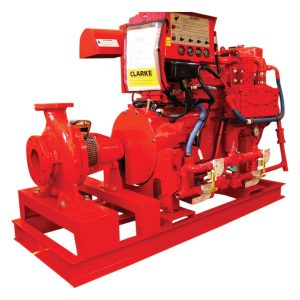
• The main and standby pumps used in the pump sets for S1, S2, and S3 buildings must be centrifugal pumps with direct coupling (close-coupled type).
• The suction line of each pump must have a shut-off valve and a strainer, and the discharge line must have a check valve and a shut-off valve.
• The suction and discharge line sizes of the main pumps in office and residential buildings must be at least 2½ inches, and if the building has a commercial use, they must be at least 3 inches. If this size differs from the pump’s suction or discharge inlet size, an appropriate reducer must be used. The size of valves and fittings must match the line sizes.
• The suction manifold size must be at least 5 inches with a minimum thickness of 3.4 millimeters, and the discharge manifold must be at least 4 inches with a minimum thickness of 3.05 millimeters.
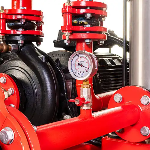
• Each pump must have a separate pressure switch. It is permissible to install all pressure switches on the pump discharge manifold. Additionally, the pump assembly must be equipped with an oil-filled pressure gauge with a dial of at least 6 centimeters on the discharge manifold.
• The use of a pressure tank in the pump assemblies of S1, S2, and S3 is not mandatory.
• All components of the pump assembly must be installed and fixed on a steel chassis. The chassis should be made from a channel section with a minimum size of 6 (units). The chassis must extend beneath the suction manifold, and the suction manifold should be secured to the chassis at two points using appropriate supports.
• To prevent damage caused by earthquakes, metal accordion-type vibration isolators must be installed on the suction and discharge manifolds of the pumps (at the connection points to the suction line from the tank and the riser).
• After the completion of manufacturing and assembly, the pump assembly must undergo a hydrostatic test under a minimum pressure of 14 bar for a duration of 2 hours.
• Each of the main and reserve pumps must be equipped with a bypass line fitted with a safety valve or a suitably sized rupture disc. Additionally, the discharge collector should have a test and drain branch with a size of ½ inch.
• Electrical panels (including the panel box and internal rails for equipment installation) must be made of steel sheets with a minimum thickness of 1 mm, and be equipped with a lock, hinge, cover, and mounting lugs. They should be coated with electrostatic powder coating (baked finish).
• The interior space of the control panel must be designed to allow easy access to internal equipment for inspection and maintenance. This space should also be planned in a way that provides at least 15% capacity for future expansion.
• The electrical circuit must be designed in such a way that, in the event of a pressure drop and the activation of any of the pumps during a fire condition, the pump’s operation does not stop even if the pressure rises back to the set value, and it continues running for at least 10 minutes.
• The pump set control panel must be connected to the fire detection and alarm system with the capability to receive fire and fault commands. This connection must be configured so that both fault and fire status signals from the electrical panel are transmitted to the fire alarm panel.
• The panel must be equipped with a phase control relay. This relay must be connected to an air siren mounted on the panel body. In the event of a phase control fault, the siren must be activated and should not shut off automatically until the fault is resolved. The siren should only be turned off manually by the operator.
• The use of overcurrent protection devices in the power circuits of the main pumps is not permitted.
• Direct-on-line (DOL) starting of electric motors is permitted for pumps with power up to 7.5 kW. For higher power ratings, the star-delta starting method must be used.
محسن زارعی –
محصولاتتون فوق العاده باکیفیت هستند.